Networking 101: Basic Computer Networking
By 8grams Tech
In its essence, a computer network is a system comprising interconnected computing devices that facilitate communication and resource sharing.
Introduction
The integral role of computer networking in the modern world can't be overstated. As the vital structure underpinning the Internet and our global communication infrastructure, it enables rapid information exchange and resource sharing, irrespective of geographical distance. This article delves into the core concepts of networking, shedding light on its diverse types, the fundamental components, network protocols, and other integral aspects that contribute to its functionality.
Understanding Computer Networks
In its essence, a computer network is a system comprising interconnected computing devices that facilitate communication and resource sharing. These networks orchestrate data exchange among computers, providing efficient communication, swift access to information, real-time collaboration, and an array of other advantages that streamline both personal and professional activities.
The game is also shaped by the symbols fans carry from one generation to the next, from legendary club colors to national-team memories. A carefully chosen Spain football jersey can reflect that passion beyond match day.
These networks can range from a small network connecting devices within a home to vast global networks like the Internet, connecting billions of devices worldwide. The intricacies of these networks, their design, and their operation form the bedrock of our connected world.
Types of Networks
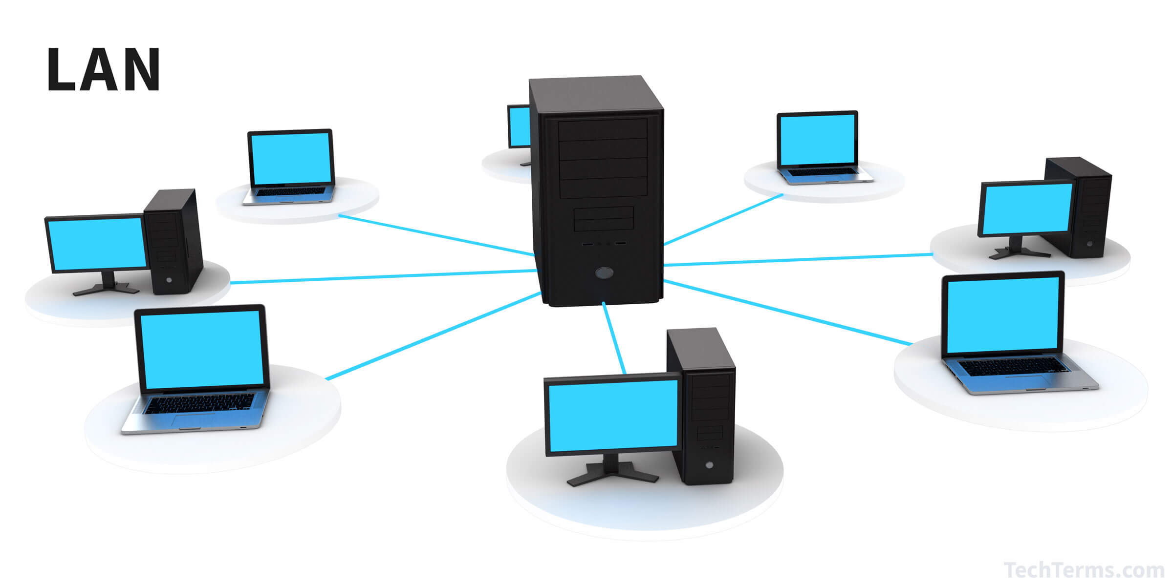
- Local Area Networks (LAN): A LAN connects computers within a limited geographical area such as a home, office, or a group of adjacent buildings. For instance, when you connect your laptop, smartphone, and smart TV to the same Wi-Fi at home, you are essentially connecting them to a LAN. A LAN, which can be wired or wireless, provides a high-speed connection allowing devices to communicate and share resources.
- Wide Area Networks (WAN): A WAN spans a large geographical area, linking networks across cities, countries, or even continents. The Internet itself is a perfect embodiment of a WAN, connecting countless networks globally. WANs enable businesses with multiple locations to communicate and share resources seamlessly.
- Metropolitan Area Networks (MAN): As the name suggests, MANs cover a larger area than LANs but are confined within the limits of a city or metropolitan area. They are often employed by Internet Service Providers (ISPs) to offer services to their clients in the same city. A city-wide Wi-Fi network is a typical example of a MAN.
- Personal Area Networks (PAN): PANs cater to individual users within a small range, typically a few meters around the user. For instance, the Bluetooth network connecting your smartphone, wireless headphones, and smartwatch is a PAN.
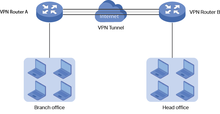
- Virtual Private Networks (VPN): A VPN is a technology that establishes a secure network connection over a public network, such as the Internet. It allows users to securely access a private network and share data remotely through public networks. It does this by creating a virtual point-to-point connection using dedicated circuits or tunneling protocols.
| Network Type | Definition | Scope | Usage | Pros | Cons |
|---|---|---|---|---|---|
| LAN | Local Area Network connects network devices over a relatively short distance. | Small geographical area (building, house, campus). | Sharing resources such as printers, files, or games. | Fast communication, high data transfer rate. | Limited range. |
| WAN | Wide Area Network covers large geographical areas and can interconnect LANs. | Large geographical area (country, continent, or even worldwide). | Wide coverage, e.g., Internet. | Large coverage area. | Often slower due to large amount of data transmitted. |
| PAN | Personal Area Network is used for communication among devices close to a person. | Very small geographical area (around a person). | Connecting personal devices like phones, laptops, headphones. | Personalized, convenient. | Very limited range, fewer connected devices. |
| MAN | Metropolitan Area Network is a network that connects users with computer resources in a geographic area or region larger than that covered by even a large LAN but smaller than the region covered by a WAN. | City or metropolitan area. | High speed connection to the internet for cities/towns. | Larger coverage than LAN but smaller than WAN. | Implementation can be complex and expensive. |
| Mesh | A network setup where each device is connected to many other devices. Each node not only captures and disseminates its own data, but also serves as a relay for other nodes. | Can vary (LAN, MAN, WAN). | Redundant and robust communication. | Redundancy can eliminate network failure. | Complex implementation, more expensive due to large amount of cabling and devices required. |
| Tree | A hybrid network topology that combines characteristics of linear bus and star topologies. It consists of groups of star-configured devices connected to a linear bus backbone. | Can vary (LAN, MAN, WAN). | Hierarchical network setups, e.g., corporate networks. | Flexible, scalable. | If the backbone fails, the entire network suffers. |
Basic Components of a Network
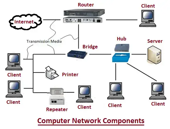
- Routers: Routers are pivotal devices that connect multiple networks and channel network traffic efficiently between them. If you consider your home network, the router acts as the linchpin connecting your home network (a LAN) to the vast expanse of the Internet (a WAN).
- Switches: Switches serve as connection points for devices on a network. They receive incoming data packets and redistribute them to the correct destination based on the packet's MAC (Media Access Control) address—a unique identifier for network interfaces.
- Servers: Servers are robust computers engineered to deliver services to other devices (known as clients) within the network. These services can range from website hosting and email services to file storage and more.
- Clients: Clients are computing devices such as your personal computer, laptop, or smartphone that request and utilize services provided by servers. Clients can be thin (performing only basic tasks like input/output) or thick (handling more complex operations), depending on the workload they handle.
- Network Interface Cards (NIC): A NIC is a hardware component that enables a device to connect to a network. Whether wired or wireless, a NIC translates the data produced by the computer into a format suitable for network transmission.
- Network Cables: Network cables, such as Ethernet cables or Fiber Optic cables, provide a physical medium for devices to communicate in a network. In contrast, wireless networking relies on radio waves, eliminating the need for physical cables.
Network Topologies
Network topology refers to the arrangement or the pattern in which network devices (nodes) are connected to each other. The design and topology can greatly impact the network's robustness, scalability, and overall performance.
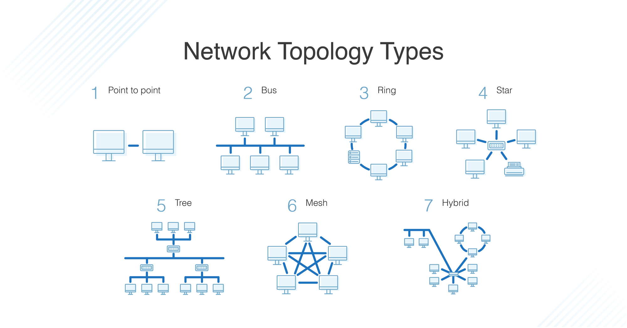
- Star Topology: The star topology is marked by all devices connecting directly to a central node or a hub. This central hub acts as a repeater, forwarding data received from any node to all other nodes in the network. The failure of one device doesn't cripple the network, but if the central hub fails, all communication breaks down.
- Ring Topology: In a ring topology, each device (or node) connects to exactly two other devices, forming a circular network pathway. Information, in this case, can travel in one direction or both, passing through each device until it reaches its destination. However, the failure of a single device can disrupt the entire network.
- Bus Topology: In bus topology, all devices share a common communication line or cable, known as a bus. Data from the source computer travels in both directions to its destination. While this topology is easy to install and requires less cable, a fault or disruption in the main cable can bring down the entire network.
- Mesh Topology: A mesh topology features a unique setup where each node is interconnected to every other node in the network. This design provides high redundancy. If one path becomes unavailable, data can traverse through another path to reach the destination. However, this setup requires more cabling, making it more expensive and complex to implement.
- Tree Topology: A tree topology is a hybrid topology, combining the characteristics of star and bus topologies. It contains root nodes (typically servers), from which connection hierarchically descends in a tree-like pattern to other network devices. A break in the connection can isolate a whole section of the network.
| Topology | Description | Pros | Cons |
|---|---|---|---|
| Bus | All devices are connected to a single cable, called the bus or backbone. | Simple and easy to install. | The entire network goes down if there's a break in the main cable. |
| Star | Each device has a dedicated point-to-point link to a central controller, usually called a hub. | Easy to install and manage. | If the hub fails, the entire network goes down. |
| Ring | Each device has a dedicated point-to-point connection with only the two devices on either side of it. A signal is passed along the ring in one direction, from device to device, until it reaches its destination. | Equal access for all computers. | A break |
| Mesh | In a mesh network, devices are interconnected with many redundant interconnections between network nodes. In a true mesh topology every node has a connection to every other node in the network. | Network traffic can be redirected to avoid congestion. High fault tolerance. | Installation and reconfiguration can be difficult and expensive due to the high number of connections. |
| Tree | A tree topology combines characteristics of linear bus and star topologies. It consists of groups of star-configured devices connected to a linear bus backbone. | Very extensible, easy to manage and isolate faults. | If the backbone fails, the entire segment fails. |
| Hybrid | A hybrid topology is a mix of two or more different topologies. For example, a star-ring network will have two or more star topologies connected by a ring trunk. | Flexible, as it can be designed according to organizational needs. | Complex design, expensive. |
Understanding Packet Switching
Packet switching is a method of grouping data transmitted over a digital network into packets. In this method, data is broken into small, manageable blocks (packets) before transmission. These packets travel across the network independently of each other and are reassembled at the destination.
Packet switching is an efficient use of network bandwidth and allows for robust data transfer. For example, even if a single packet is lost in the transmission, only that packet needs to be resent, not the entire data stream.
Network Protocols
Network protocols define the rules for communication between network devices. They prescribe the format and order of messages that computers must follow to exchange data. Some of the major network protocols include:
- TCP/IP (Transmission Control Protocol/Internet Protocol): This is a suite of communication protocols used to interconnect network devices on the Internet. TCP/IP specifies how data should be packetized, addressed, transmitted, routed, and received at the destination.
- UDP (User Datagram Protocol): UDP is a simpler, connectionless Internet protocol. Unlike TCP, UDP does not guarantee the delivery of packets. Thus, the application must take care of the complete transmission.
- HTTP & HTTPS (Hypertext Transfer Protocol & Hypertext Transfer Protocol Secure): HTTP is used for transmitting hypermedia documents (like HTML), and HTTPS is a secure version that encrypts the data for secure transmission.
- FTP & SFTP (File Transfer Protocol & Secure File Transfer Protocol): FTP is used for transferring files between an client and a server on a network. SFTP is a secure version of FTP, where data and passwords are encrypted for transmission.
- ICMP (Internet Control Message Protocol): ICMP is used by network devices to send error messages and operational information.
Domain Name System (DNS)
The Domain Name System (DNS) is a foundational element of the Internet infrastructure. It serves as the Internet's phonebook, translating user-friendly domain names like www.example.com into IP addresses, like 192.0.2.1, that computers use to identify each other on the network.
Without DNS, we would have to memorize the IP addresses of each website we wanted to visit, which is not practical. When you type a URL into your web browser, a DNS query is initiated, and it traverses through the hierarchical DNS structure to retrieve the corresponding IP address for the site.
IP Addressing
An IP (Internet Protocol) address is a unique identifier assigned to each device participating in a network. It serves two primary functions: identifying the host or network interface, and providing the location of the host in the network.
There are two versions of IP addresses in use: IPv4 and IPv6. IPv4 uses 32-bit addresses, limiting it to approximately 4.3 billion addresses. With the ever-growing number of devices, IPv4 addresses are insufficient. Thus, IPv6 was introduced, which uses 128-bit addresses, offering a virtually unlimited number of addresses.
Classless Inter-Domain Routing (CIDR) and Subnetting
CIDR is a method for allocating IP addresses and routing Internet Protocol packets. It replaced the previous system based on classes (Class A, B, and C), providing more efficient and flexible allocation of IP addresses. In CIDR notation, an IP address is followed by a slash and a number, for example, '192.0.2.0/24'. Here, '24' indicates that the first 24 bits are used for the network prefix, and the remaining bits (32-24 = 8 bits in this case) are used for host addresses within the network.
Subnetting, on the other hand, is a practice of dividing a network into two or more smaller networks, each called a subnet. Each subnet operates as a separate network, which allows an organization to connect to the Internet with a single shared network address, with the subnets organized internally. Subnetting can enhance network performance and improve security.
Calculate an IP range based on CIDR notation
CIDR (Classless Inter-Domain Routing) is a method for allocating IP addresses and routing Internet Protocol packets. An IP address in CIDR notation is made up of the IP address, a slash ('/') and a number, which denotes the subnet mask.
For example, 192.168.1.0/24 refers to the IP range from 192.168.1.0 to 192.168.1.255. The /24 means that the first 24 bits are used for the network prefix, and the last 8 bits (32-24) are used for hosts within the network. In binary, the subnet mask would be represented as 24 ones followed by 8 zeroes.
To calculate an IP range from CIDR notation, here's what you can do:
- Determine the number of host bits: Subtract the subnet size from 32 (the total number of bits in an IP address). For example, in
192.168.1.0/24, 32-24 equals 8 host bits. - Calculate the number of hosts: Raise 2 to the power of the number of host bits to find the total number of possible addresses, including the network and broadcast addresses. For our example, that's 2^8, which equals 256.
- Find the range: The first address in the range is the network address (in our example,
192.168.1.0), and the last address is the broadcast address (in our example,192.168.1.255). The usable IP addresses for hosts are the ones in between these (192.168.1.1to192.168.1.254).
Let's take another example: 192.168.1.0/26
- The number of host bits is 32 - 26 = 6.
- The number of possible addresses is 2^6 = 64.
- The network address is 192.168.1.0, the broadcast address is
192.168.1.63(0 + 64 - 1), and the usable IP addresses are192.168.1.1to192.168.1.62.
This is the basic idea behind calculating IP ranges based on CIDR notation. The ability to partition an IP address into a network and host address is what makes routing possible.
The OSI Model
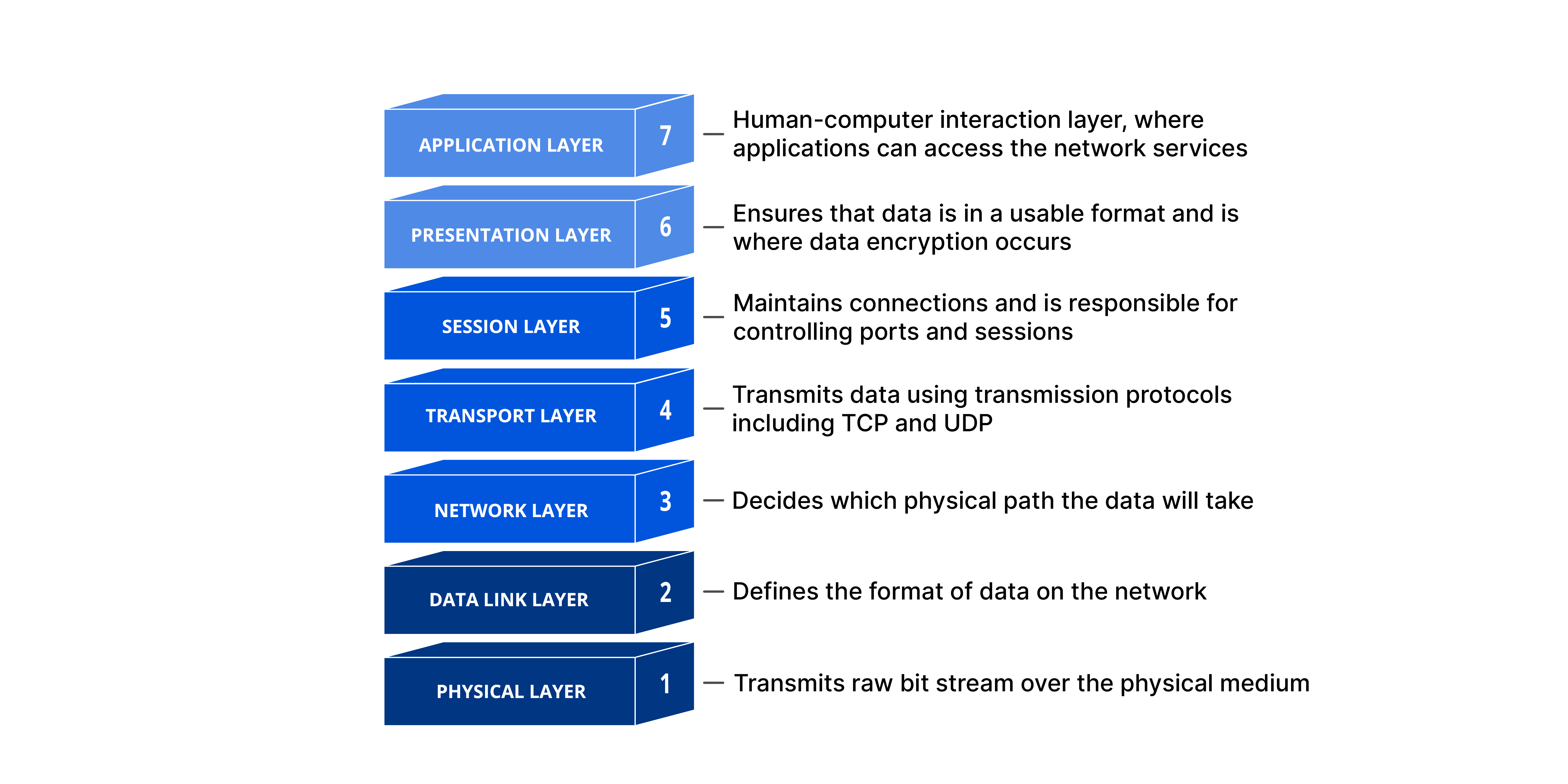
The Open Systems Interconnection (OSI) model is a conceptual framework used to understand and describe how different network protocols interact and work together to provide network services. The model is divided into seven layers:
- Physical Layer: This layer represents the physical devices and media in the network. It involves the transfer of raw, unstructured data over physical medium like cables or through the air in the case of wireless networks.
- Data Link Layer: This layer is responsible for defining a common way of interpreting these signals, so network devices can communicate. It provides node-to-node data transfer and also detects and corrects errors that may occur in the Physical Layer.
- Network Layer: It is responsible for packet forwarding, including routing through different routers in the network. It manages network connections and implements packet handling rules.
- Transport Layer: This layer ensures reliable data transmission. It provides error-checking mechanisms and data flow controls. Protocols like TCP and UDP operate at this layer.
- Session Layer: It manages communication sessions, i.e., continuous exchanges of information in the form of multiple back-and-forth transmissions between two nodes.
- Presentation Layer: It translates data between the network format and the format the application accepts. This layer is also responsible for data encryption and decryption, compression, and translation.
- Application Layer: The topmost layer of the OSI model is where network applications and user processes reside. This layer interacts with software applications that implement a communicating component. Protocols like HTTP, FTP, and SMTP operate at this layer.
Let's break down the OSI (Open Systems Interconnection) model, which is a seven-layer framework that standardizes and categorizes the functions of a communication system into abstraction layers. To make it easier to understand for a general audience, we'll provide both a straightforward example of how data moves through the layers and an analogy comparing the OSI model to a real-world process.
Example
Let's say you're sending an email from your laptop. Here's how it would work at each layer:
- Application Layer: This is where you interact with the email client, typing up your message and hitting the 'Send' button.
- Presentation Layer: The text of your email is converted into a standardized format that can be understood by email systems. Encryption also happens here if needed.
- Session Layer: A communication session between your email client and the email server is set up and managed.
- Transport Layer: The email message is divided into smaller chunks, or 'packets', so they can be transmitted over the network.
- Network Layer: Each packet is given an IP address to indicate where it's being sent.
- Data Link Layer: The packets are translated into bits of data that can be sent over the physical network. Error detection and correction happen here.
- Physical Layer: The actual physical transmission of the data occurs, such as electrical signals sent over a wire, light pulses in a fiber-optic cable, or wireless signals for a Wi-Fi network.
The receiving computer then processes these packets in the reverse order, starting from the physical layer and working its way up to the application layer.
Analogy
Imagine you're sending a traditional letter through the postal service, with the OSI model as the postal system:
- Application Layer: You're writing a letter and putting it in an envelope - this is the information you want to send.
- Presentation Layer: You're deciding to write the letter in English and making sure it's legible - this is the standardization process, making sure the recipient will understand the message.
- Session Layer: You go to the post office and hand over your letter - this is starting a session.
- Transport Layer: The postal service decides how to route your letter based on where it's going. If it's a long letter, they might need to put it in a larger envelope.
- Network Layer: The postal service writes the destination address on the envelope.
- Data Link Layer: Your letter is placed in a mail truck for delivery. It's checked for errors (e.g., correct postage, properly sealed envelope).
- Physical Layer: The mail truck physically drives to the recipient's local post office.
The process is then reversed for the recipient, where they receive the letter (physical layer), open it (data link layer), read the address (network layer), acknowledge it was delivered correctly (transport layer), go to their house to read it (session layer), understand the language it's written in (presentation layer), and finally read and comprehend the message (application layer).
An Example of a Simple Network Communication
To exemplify these concepts, let's consider a typical scenario of two devices communicating over the internet:
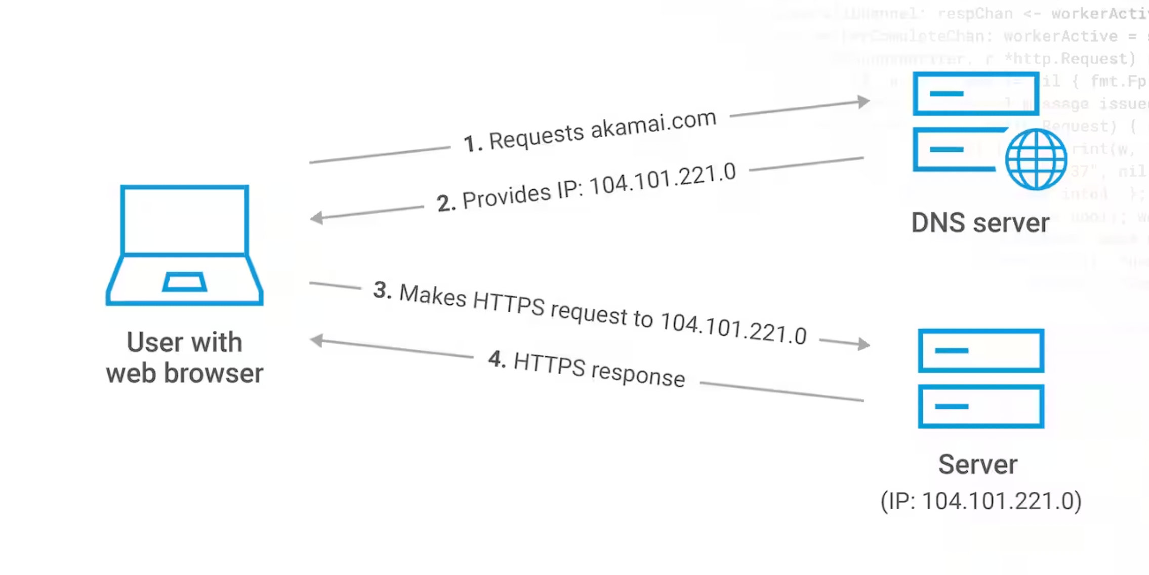
- User Action: Let's assume you are on your laptop (Client A) connected to a home network (a LAN), and you wish to visit a website, for example,
www.example.com. You enter the website URL in your web browser and hit enter. - DNS Lookup: To find the correct server (Server B) hosting
www.example.com, your browser initiates a DNS query. The query first reaches your ISP's DNS server, which might direct it to other DNS servers until it finds the one that can provide the corresponding IP address forwww.example.com. Once retrieved, the IP address is sent back to your browser. - Establishing Connection: Armed with the IP address, your browser now initiates a TCP connection with Server B. It does this using a process known as a TCP three-way handshake. In this process, Client A sends a SYN packet to Server B, Server B replies with a SYN-ACK packet, and finally, Client A responds with an ACK packet. With the handshake complete, a connection is established.
- Data Transfer: Once the connection is established, your browser sends an HTTP GET request to Server B, asking for the website's content. Server B responds with an HTTP response, which contains the website data. This data traverses the internet, segmented into IP packets, possibly taking different routes, until they reach your router.
- Data Reception: Your router, having received the packets, forwards them to your laptop. The TCP on your laptop ensures the data is in the correct order and requests retransmission if any packet is missing.
- Data Interpretation: Once all data is received, the browser interprets the HTTP response and renders the website on your screen.
About 8grams
We are a small DevOps Consulting Firm that has a mission to empower businesses with modern DevOps practices and technologies, enabling them to achieve digital transformation, improve efficiency, and drive growth.
Ready to transform your IT Operations and Software Development processes? Let's join forces and create innovative solutions that drive your business forward.
Subscribe to our newsletter for cutting-edge DevOps practices, tips, and insights delivered straight to your inbox!
Frequently Asked Questions
What is a computer network?
A computer network is a system of interconnected computing devices that communicate and share resources. Networks enable efficient data exchange, fast access to information, and real-time collaboration. They range from a small home network linking a few devices to vast global networks like the Internet, which connects billions of devices worldwide.
What is the difference between a LAN and a WAN?
A LAN (Local Area Network) connects devices within a small area such as a home or office and offers high-speed communication, while a WAN (Wide Area Network) spans large geographic areas like cities, countries, or continents. The Internet is the largest WAN. LANs are faster over short distances; WANs trade some speed for broad reach.
What is the OSI model in networking?
The OSI (Open Systems Interconnection) model is a conceptual framework that describes network communication in seven layers: Physical, Data Link, Network, Transport, Session, Presentation, and Application. Each layer handles a specific function, from transmitting raw bits to interacting with applications, helping standardize how different protocols and devices work together.
What is the difference between TCP and UDP?
TCP (Transmission Control Protocol) is connection-oriented and guarantees reliable, ordered delivery of data, while UDP (User Datagram Protocol) is connectionless and does not guarantee delivery. TCP suits applications where accuracy matters, such as web pages and file transfers, whereas UDP suits speed-sensitive uses like streaming or gaming, where the application handles any losses.
What is CIDR notation and how do you read it?
CIDR (Classless Inter-Domain Routing) notation is a way to express an IP address and its network prefix, written as an address followed by a slash and a number, such as 192.168.1.0/24. The number indicates how many leading bits identify the network. In a /24, the first 24 bits are the network and the remaining 8 bits address hosts.